


Hersteller von DC/DC Wandler, DC/DC Regler und PoL (Point-of-Load) Wandler
Aufgaben und Funktionen von Gleichspannungswandlern
Die Hauptaufgabe eines DC/DC Wandlers liegt darin, eine Gleichspannung auf eine andere Gleichspannung umzusetzen. Im Vergleich zur Eingangsspannung kann die Ausgangsspannung dann tiefer, höher, invertiert und/oder isoliert sein. Weiterhin werden DC/DC Konverter auch zur Auffrischung einer DC-Spannung oder eines DC-Signals an langen Zuleitungen eingesetzt. Hierbei ist zu beachten, dass man einen Wandler mit einem weiten Eingangsspannungsbereich einsetzt.
DC/DC Wandler - mit galvanischer Trennung
Galvanisch getrennte DC/DC Wandler wandeln eine Gleichspannung am Eingang in eine Gleichspannung am Ausgang um. Wobei eine Isolation zwischen Eingang und Ausgang unterschiedliche Potentiale ermöglicht. Die typische Isolationsspannung liegt zwischen 500Vdc und 4kVdc. Darüber hinaus verhindert die Isolation im „Worst Case“ eine Umwandlung von der Eingangs- zur Ausgangsspannung.
Hauptvorteile des galvanisch getrennten Wandlers
• Unterschiedliche Ein- / Ausgangspotentiale erlaubt
• Besserer Personenschutz

DC/DC Regler und POL Wandler - ohne glavanische Trennung
Unisolierte (das heisst galvanisch nicht getrennte) Gleichspannungswandler haben keine Isolation zwischen Eingang und Ausgang.
Der Eingang muss daher dasselbe Potential aufweisen wie der Ausgang. Vorteile des Reglers sind die hohe Leistungsdichte sowie der hohe Wirkungsgrad aufgrund der geringeren Anzahl an Komponenten.
Hauptvorteile des unisolierten Reglers
• Sehr hoher Wirkungsgrad
• Kompaktes Design
 ohne galvanische Trennung")
Unregulierte DC/DC Wandler
Unregulierte DC/DC Wandler haben keinen direkten Abgleich zwischen der effektiven Ausgangsspannung und der nominalen Spannung. Daher fehlt ihnen die Möglichkeit, einen Spannungsfall der Ausgangspannung ausgelöst von einer Lastzunahme direkt zu kompensieren. Oftmals wird ein indirekter Spannungsabgleich verwendet mit einer typischen Lastregulierung von ±15 bis ±20% der nominalen Ausgangsspannung.
Hauptvorteile des unregulierten Wandlers
• Kosteneffizientes Design
• Kompaktes Design

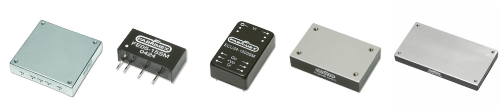
Baugrössen
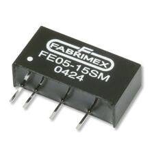
DC/DC Wandler DIP8 Baugrösse
Leistung: 1 - 3 Watt
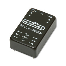
DC/DC Wandler DIP24 Baugrösse
Leistung: 3 - 15 Watt
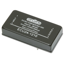
DC/DC Wandler 2x1" Baugrösse
Leistung: 15 - 30 Watt
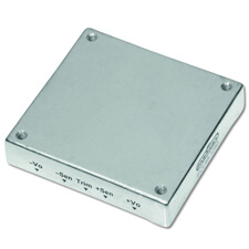
Quarter-Brick Baugrösse
Leistung: 30 - 100 Watt
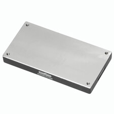
Half-Brick Baugrösse
Leistung: 50 - 350 Watt
Single / Dual Output
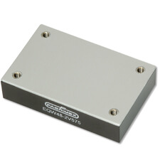
Full-Brick Baugrösse
Leistung: 200 - 700 Watt
Temperatur Schutz
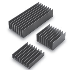
Kühlkörper
Für Quarter- / Half- / Full-Brick
Terminology
Below you will find a list of common DC/DC terminology which may appear in the data sheets. The terminology, with a brief corresponding explanation, is in alphabetical order and the list will be updated on regular base.
A - B - C - D - E - F - G - H - I - J - K - L - M - N - O - P - Q - R - S - T - U - V - W - X - Y - Z
A
Approval
Many power supplies have to meet certain standards. If so, these are listed in the data sheet. However, many standards apply only on an apparatus level. Then a Fabrimex will not list this under “approvals” in the data sheet, but the adherence to that standard can be found in the relevant technical parameter.
Ambient Temperature (Ta)
The temperature in the medium around a component is measured some distance from the power supply, usually a few cm, to be considered uniform. However, ambient temperature is per definition imprecise . Therefore temperature ratings for converters are usually given for case temperatures (Tc).
Top
B
Boost Converter
The boost converter (step-up) is a commonly used building block in converter design without galvanic isolation. When the switch (Q) is conductive, the inductor (L) is charged. After opening the switch the energy is transferred from the inductor to the load.
The output-to-input voltage ratio is always greater than one and is ideally equal to the inverse of one minus the duty conduction cycle of the switch during continuous operation. The boost topology also requires an output energy storage capacitor to support the load current while the switch is on.
Brownout
Partial power outage. The input voltage drops below the minimum input voltage of a connected load. The result is a drop of the output voltage below the nominal value.
Buck Converter
The Buck Converter (step-down) is another commonly used building block in converter designs without galvanic separation. In its basic form, without a transformer, the output voltage is always less than the input voltage.
When the transistor (Q) is switched on, energy is transferred from the input source to charge the inductor (L) and the output. When the switch is turned off, the inductors polarity is reversed and the energy is transferred to the output capacitor and the load. The output-to-input voltage ratio is ideally equal to the conduction duty cycle of the switch for continuous operation. Since most applications severely limit the amount of pulsating current that can be drawn from the converter’s input source, some form of low pass filter is generally inserted on the input side of the switch.
Burn-In
The process of operating newly manufactured power supplies for some period of time prior to delivery. The intent is to stabilize the electronics and eliminate infant mortality by aging the device. The time period and conditions (input voltage cycling, load switching, temperature, etc.) can be varied.
Burst
High-frequency and low-power impulse, capacitive coupled via an electrical field.
Top
C
Case Temperature
The temperature of a converter measured at its hottest spot on the base plate or case. Temperature ratings for converters are usually given for the case temperature (Tc), as ambient temperature per definition is imprecise. The case temperature for an operating converter is ordinarily higher than the ambient temperature.
Convection Cooling
Cooling without forced air flow, also referred to as ‘natural convection’. The only air flow is induced by temperature differences rather than by mechanical means
Converter Regulated
A DC/DC converter where the output voltage value, independent of the load and input voltage, is regulated within specified limits.
Converter Unregulated
A DC/DC converter where the output voltage value changes depending on the load and input voltage.
Crow Bar
An over voltage protection circuit which monitors the output voltage of a power supply and rapidly creates a low resistance path, usually a thyristor, across the output when a predetermined voltage is exceeded.
Current Limit
A protection of the power supply where the output current is limited to a value above the nominal output current, usually between 110% to 150% of the nominal output current
Top
D
Derating
Temperature derating allows the operating temperature to exceed the specified values if the output power is reduced as predetermined (reciprocal, the output power may exceed the specified nominal power if the operating temperature is reduced as predetermined).
Dynamic Load Response
Voltage jump at the output caused by a jump in the load current. See also: Load Transient Recovery Time, Load Transient Error Band.
Top
E
Efficiency (η)
Ratio between output power and input power as a factor or a percentage.
η=PoutPin
or
η=PoutPin×100 %EMC (in general)
The electromagnetic compatibility (EMC) of equipment is understood to mean
a) the limitation of the transmission of electromagnetic interference to a level that guarantees trouble-free operation of other equipment in the environment (EMC conducted and / or radiated)
b) the ensuring of a sufficiently high resistance to externally acting electromagnetic interference so that correct operation is guaranteed at the intended place of use under the electromagnetic interference conditions to be expected there (EMC irradiated).
EMC Irradiated
Electromagnetic interference caused by externally acting factors which penetrate the power supply
EMC Radiated
Electromagnetic interference caused by the power supply and which is transmitted via the surrounding medium (air)
Top
F
Flyback Converter
The Flyback Converter is used in circuits with galvanic isolation for lower power ranges. In the basic Flyback Converter, when the transistor is turned on, the current increases linearly in the transformer (T) primary and is stored in a magnetic field. When the switch (Q) turns off the transformer, its polarity is reversed and causes a current flow in the secondary, transferring energy to the output capacitor and the load.
Since the transformer assumes the roles of both an energy storage device and a transformer, only one magnetic component is needed.
Fold Back Curve
This current limiting characteristic decreases the output current and voltage simultaneously as the overload increases to protect the load
When in current limiting mode, the converter usually has to be re-started to escape the current limiting mode.
Forward Converter
The Forward Converter is a circuit with galvanic isolation for low power. Contrary to the Flyback, the Forward Converter is not storing energy in the transformer. The secondary winding is in opposite direction, compared to the Flyback. It carries the current immediately to the secondary side. The energy is stored in the succeeding inductor.
Full Bridge Converter
The Full Bridge topology is a derivate of the Forward Converter, intended for higher power, also with galvanic isolation. The transformer (T) is alternately connected to the full input voltage. Two of the four transistors (Q) are building one branch (Q1/Q4 or Q2/Q3), and each branch is driven alternated. Similar to the Forward Converter, the transformer transfers the energy directly to the inductor on the secondary side.
Top
G
Top
H
Half Bridge Converter
The Half Bridge topology is a derivate of the Forward Converter for mid power, also with galvanic isolation. The transformer (T) is connected to the midpoint between the two capacitors (C1/C2). The two transistors are driven alternated and charge the transformer with different polarities. Similar to the Forward Converter, the transformer transfers the energy directly to the inductor on the secondary side.
Hold-Up Time
The amount of time that a power supply's output remains within the specified output voltage range after its input voltage ceases.
Top
I
Input Voltage Range
The range of input voltage values for which a power supply operates within specified limits.
Inrush Current
The maximum input current drawn by a power supply when turned on. The lower the current, the less thermal shock the system experiences.
Isolation Resistance
The resistance between input and output, primarily a function of the transformer used. The isolation resistance is useful when the leakage current between input and output has to be established.
Isolation Voltage
Also known as galvanic isolation voltage. The maximum AC or DC voltage which can be applied to the power supply between input and output while the specified isolation resistance is maintained. Primarily a function of the transformer used.
Top
J
Top
K
Top
L
Leakage Current
A term relating to current flowing between the AC supply wires and earth ground. Leakage current usually refers to the 50/60 Hertz current which flows through the EMI filter capacitors which are connected between the AC lines and ground.
Line Regulation
The maximum deviation, in percentage of nominal, of the output voltage when the input voltage varies from minimum to maximum.
Load Regulation
The maximum deviation, in percentage of nominal, of the output voltage when the load varies from a determined minimum to maximum.
Load Transient Recovery Time
Time needed to enter the specified output voltage range after a jump in the load current.
Load Transient Error Band
Defined output voltage range outside the specified range, caused be a jump in the load current.
Top
M
MTBF
MTBF (Mean Time Between Failures) is a factor to express the likelihood of failures and the unit is in operating hours. This factor is a statistical factor and can not be applied to a single power supply only, but has to applied to a multitude.
1st Failure = MTFB / quantity [h]
There are several MTBF standards, such as the MIL-HDBK-217 and the Belcore standard. The MTBF values of different standards can not be directly compared to each other.
Top
N
Natural Convection
No Load Current
Also referred to as ‘standby current’, is the input current the power supply will consume when no load is connected to the output.
Top
O
Open Frame
AC/DC and DC/DC modules where the components are in direct contact to the air flow as opposed to potted or enclosed modules. Advantage of open frame modules is the exposed surface area to the airflow which is larger then of a potted module.
Overvoltage Protection
A protective feature which either shuts down the power supply or crowbars the output in the event of an over voltage condition at the output.
Output Voltage Accuracy
The maximum deviation, in percentage of nominal, of the output voltage at nominal conditions.
Operating Temperature
The temperature range the power supply will operate within (including start up), inside of the specified limits. The operating temperature can be defined as ambient temperature (Ta) or case temperature (Tc).
Output Voltage Trim
Also known as “output voltage adjustment” and is used to make small adjustments to the nominal output voltage, usually ±10%. For board mounted modules it usually is an external adjustment, a resistance connected to a pin. Other power supplies can feature a potentiometer which can be adjusted mechanically with a screw driver.
Top
P
Polarity Protection
A feature which protects the input of the dc/dc converter if the applied polarity has been interchanged.
Potting
A method of packaging board mounted modules as opposed to open frame modules. Advantage of potted modules is the thermal capacity characteristic of the potting which will transfer the heat from hot spots efficiently. Further the potting protects against mechanical influences.
Power Dissipation (Pd)
Also referred to as “thermal power”, is the difference between input and output power. The power dissipation is converted to heat inside the power supply. To keep internal die-junction temperatures within normal operating specifications maximum power dissipation limits are specified. Power dissipation is calculated as follows:
Pd=Pin- Pout
or
Pd=Pout×(1-η)η WPush-Pull Converter
The Push-Pull topology is a derivate of the Forward Converter for mid power, also with galvanic isolation. The two transistors (T) are driven alternated. Thus, the magnetic field -flow through the windings is also alternated. Similar to the Forward Converter, the energy is stored in the succeeding inductor (L).
PWM
Pulse width modulation (PWM) regulates the output voltage in switching power supplies whereby the output voltage is controlled by varying the width, but not the height, of a train of pulses which trigger a power switch.
Top
Q
Top
R
Rca, Rth
Remote Sense
A feature where the voltage drop between the power supply and the load is automatically compensated if the sense is connected to the load.
Ripple & Noise
Ripple is the triangle waveform on top of the output voltage, generated by the PWM. Therefore the ripple presents the same frequency as the power supplies switching frequency.
Noise are the spikes at a given bandwidth on the output voltage as a result of conducted line noise, internal switching transients and other random noise
Top
S
Short Circuit Protection
Protection against damage to the power supply if the load becomes shorted. When ‘continuous’ short circuit protection, the power supply will resume operation automatically once the short circuit is removed. The main short circuit characteristics are ‘hiccup mode’ and ‘current limit’.
Soft Start
A feature used for inrush current limiting of the power supply during start up, causing the output voltage to rise gradually to its specified level.
Surge
Low-frequency and high-power impulse, inductive coupled via an magnetic field.
Stand-by Current
See No Load Current
Start-Up Time
The time required until the output voltage reaches a certain percentage of nominal after input voltage has been switched on.
Step-Up Converter
See Boost Converter
Storage Temperature
The minimum temperature range the power supply can be stored at without derogating the power supplies specification.
Switching Frequency
The rate at which the internal DC voltage is switched on and off during the pulse width modulation process in a switching power supply. The switching frequency can be fixed or variable.
Top
T
Temperature Coefficient
The temperature coefficient is the relative change of the nominal output voltage when the temperature is changed by 1 K (Kelvin).
Thermal Resistance (Rca, Rth)
The measure of a material’s ability to resist heat flow. The formula for Thermal Resistance is
R=LK K/Wwhere (L) is the material’s thickness and (k) is the material’s Thermal Conductivity constant. The higher a material’s R-value, the better its thermal insulation.
Thermal Shutdown
A protection feature where the critical internal temperature is monitored and the power supply shut down if a preset value is exceeded. The thermal protection is not intended for continuous use as the shut down is initiated at a temperature > operating temperature.
Top
U
Undervoltage Lockout
Preset input voltage values when the power supply will turn on (power up) and when it will shut down (power down).
Top
V
Top
W
Top
X
Top
Y
Top
Z
Top
Note: All information is believed to be accurate and reliable. However, no responsibility is assumed by Fabrimex for its use.
